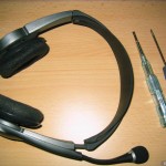
A few years ago, I bought a DSP-500 USB/digital headset from Plantronics. It’s served me well with only some minor software glitches.
It has a swivel microphone on it that has obviously only just about stood the test of time. The swivel action took its toll on my headset, and other seem to suffer the same result as well. I set about fixing mine (or at least to see if I could fix it), to save me ordering an other headset. Here’s how to disassemble the headset (assuming you have a similar fault).
- First up, have your headset ready, along with a small Phillips screwdriver, and a small flat screwdriver (or a suitable plastic priser. Obviously, unplug the headset before starting repairs!
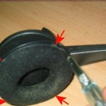
- Looking at the left earpiece (the one with the microphone), look in to the earpiece itself, and behind the foam, you’ll see where the earpiece being held by 4 clips (for the want of a better term). Prise the outer plastic away from the inner bulk of plastic at those 4 points (approximate positions arrowed in the picture below). That should release the inner plastic which forms the bulk of the earpiece.
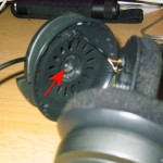
- With the earpiece assembly released, a silver screw is exposed (arrowed in the image below) at the centre. Unscrew that to release the microphone assembly from the outside of the headset.
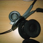
- Once disassembled, take care not to stretch the wiring (on either side of the headset assembly)
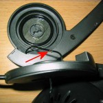
- Hopefully, you’ll see the damaged wire in roughly the same position (as this is where it’s usually kinked by the rotation of the microphone. It may be broken altogether. When working with this wire (a think co-axial wire), there are two things to keep in mind. First is that the wire is very thin and delicate, so treat it with care when stripping it. Secondly is that the outer and inner cores aren’t all that conductive (presumably because the mix of copper and other materials used) so when you’re using a standard multimeter, for example, it might not work like you expect.
- Carefully strip back the outer (black) insulation, and the inner (white) insulation. Repair, by soldering at least a few millimetres of the copper portion of each core. Be careful to adequately insulate the cores from each other. Luckily, there’s a bit of spare length in that wire to work with.
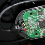
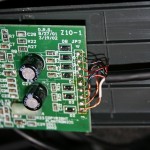
Update: As requested (quite some time ago!), I’ve added photos of the wiring in the sound-card circuit-board (that bulky Plantronics-branded box that’s inline, just above the USB plug. The wire colours are listed below, and are top-down as you’re looking at the circuit board with the printed text the right way up (i.e. “Copyright Plantronics” is down the bottom-left of the board).
For the left hand side of the circuit board (that’s the side with the USB plug), the order is bare (no colour cover), black, green, white and red. For the right side (the headset side), it’s: green, blue & copper/bare, red, green & red, blue, green & copper/bare, red & copper/bare, copper/bare (no colour), and white.
Click on the images (and then click the image on that page, again!) to see larger versions:
- Step 1: The Plantronics DSP-500 Headset
- Step 2: Unclip the earpiece assembly
- Step 3: The exposed inner screw of the earpiece
- Step 4: The earpiece assembly dissassembled
- Step 5: The damaged wire exposed
- Extra: USB plug, left-hand, side of DSP-500 circuit board
- Extra: Headset, right-hand, side of DSP-500 circuit board
Leave a Reply